
0 Warning Letter - Failure to adequately establish a procedure governing inspection and acceptance of Biological Indicators
An interesting FDA Warning Letter concerning the inspection and acceptance procedures for Biological Indicators, used in the site sterilization process. 11th October 2024 New Zealand Failure to establish and maintain procedures for acceptance activities, which include inspections, tests, or other verification activities, as required by 21 CFR 820.80(a). For example: 1) Your firm's current incoming inspection and acceptance procedure for Biological Indicator (b)(4) (BI) is not adequately established. This inadequacy could compromise the sterilization process, potentially affecting the safety and effectiveness of the NeoZoline Ventilation Tubes. Your firm discards the Certificate of Conformance provided by (b)(4) with each BI batch, which was requested by the FDA investigator during the inspection. It appears that your firm failed to retain critical documents such as the reconciliation sheet, production batch record, or (b)(4) Certification of Conformance, which are required under your own WI22 "Production QC and Release Product Register," specifically section 2.3, to demonstrate that the product was successfully sterilized. The inspection revealed that your firm does not perform BI Population verification tests on the received BI batches to ensure that the population has not changed during shipping or storage. This is a critical step is necessary to provide a high degree of assurance that the BIs are viable to support verification that finished product is successfully sterilized through the (b)(4) Sterilization process. Additionally, the inspection revealed that critical information such as the batch number and expiration date of the BI used in the sterile load is not documented on the post-sterilization B1 Test Reports, which are used as part of the finished device acceptance and release process. We reviewed your firm's response dated June 13, 2024, and conclude that it is not adequate. Your firm's response indicates that its Initial Action was completed on June 1, 2024. Your firm concluded that a risk analysis of the specific observation indicates no risk to end users for products currently in distribution and manufacturing. That conclusion is based on the following factors: The (b)(4) Biological Indicator is an off the shelf product from supplier where (b)(4) has claimed compliance with ISO 11138-1:2017 and ISO 11138-2:2017. The BI is packaged in a foil pouch designed to protect the product from humidity excursions. The pottles are used to store non-sterile Ventilation Tubes hence the sterility of the pottle is not a requirement. Additionally, your firm has outlined a plan with the following actions to be completed by December 1, 2024, which includes the following actions: (b)(4) Based on your firm's response there is an ambiguity in the definition of the term `pottle' and whether it is required to be sterile or not. (b)(4) your firm's response states that there is no risk for the sterile products manufactured at your facility because the BIs that they use conform to ISO 11138-1:2017 and ISO 11138-2:2017, and that they are in their sterile packaging until they are needed. However, the inspection demonstrated that your firm does not do any testing to verify that the BIs purchased for the purpose of demonstrating that terminal sterilization is achieved, are actually viable when they are used. Additionally, the inspection revealed that they do not capture key data such as BI batch number and expiration date, and thus if a BI falsely indicated that a sterilization was successful, there is no mechanism by which your firm can trace the lots of sterile products back to a failed BI. Additionally, your firm did not include documentation or evidence of the corrections or corrective actions because they are in progress and have not been completed. Additionally, given the observations described above, your firm has not provided a commitment to conduct a retrospective assessment of all finished devices whose sterilization was verified using Biological Indicator (b)(4) to determine whether sterility was compromised.

0 Reflections on the Devonport Incident and the Clothier Report of 1972
Over 50 years ago on the 12th July 1972, Dr Shirley Summerskill (MP for Halifax) spoke to the house of commons and said: - " It is to be deplored that human failings were the main cause of the tragedy, [in March 1972] but it is hoped that all who are concerned with the preparation of infusion fluids will take a lesson from this case. I include in that remark the management and the laboratory staff." She was of course referring to the report of the Committee which Sir Keith Joseph, Secretary of State had instructed, under the chairmanship of Mr. C. M. Clothier, QC, to inquire into the circumstances which led to the use of contaminated dextrose infusion fluids at Devonport Hospital and which involved the death of five patients. The Committee concludes—in its own words in paragraph 79 - " … that the fundamental cause of this disaster is to be found in human failings at Evans Medical, ranging from simple carelessness to poor management of men and plant. The Committee heard of no imminent technological advance in the field of production of intravenous fluids which will eliminate the need for skillful men devoted to their work. The Committee considers that too many people believe that sterilization of fluids is easily achieved with simple plant operated by men of little skill under a minimum of supervision, a view of the task which is wrong in every respect" In 2019 David Churchward a GMP inspector for the MHRA, reflecting on the Devonport incident concluded the following - "Despite significant progress in automation, there is still no replacement for a skilled and dedicated workforce who understand the importance of their work. Industry and regulators must maintain the highest levels of quality culture vigilance." "MHRA inspectors look for indicators showing that personnel at all levels of the organisation have appropriate technical knowledge to enable good decision-making and understand how their actions impact the product and patient." In his article on Quality Culture he went on to say:- A strong quality culture is built upon: knowledge of what is important, and how a process achieves critical quality attributes diligence, by fostering awareness that everyone contributes to product quality, and understanding that “my actions impact the patient and the company” vigilance by individuals who know what ‘right’ and ‘wrong’ look like in their process, and a mechanism for management to be aware of problems senior management commitment to being visible and transparent in decision-making so that positive outcomes can be seen from the diligence and vigilance efforts. This is more than the company mission statement – it’s ‘walking the talk’”. In the aftermath of the Clothier report being published the Medicines Inspectorate increased the number of inspectors, but they accepted that inspection alone would not be enough to prevent a recurrence. This position remains the same today as it did then. Around the time of the incident following a history of non-sterile products in the 1960’s the role of the regional steriliser engineer was created. Charged with the responsibility for providing technical expertise and governance to the sterilisers in their charge. This role continues today in the capacity of the Authorising Engineer (Decontamination), [AE(D)] whose role and responsibility is defined in HTM01-01 part A. [1]. They form the Decontamination Technical Platform, which constitutes registered AE(D)'s who have undergone a rigorous training framework at Eastwood Park and undergo regular peer review to ensure the high standards and expectations of IHEEM and the DTP are maintained. The DTP contributes significantly to the standards and guidance of healthcare and industry through the BSI CH198 committee for sterilization standards development; brining decades or knowledge and experience at a national and international level. [2]. In 1970 NHS Falfield (now Eastwood Park) started residential training courses for hospital engineers. This included training Test Person (Sterilisers) and the regional steriliser engineers were instrumental in the training and sharing of best practise and knowledge. This role exists today as a Competent Person (Decontamination) being defined in HTM01-01 part B, as well as the role of the Authorised Person (Decontamination), the latter responsible for the management of the decontamination and sterilisation service.[3]. Both roles are City & Guilds Accredited at Eastwood Park where AE(D)’s continue to provide robust training for hospital engineers and engineers from industry. These roles within the Healthcare setting provide assurance that the people charged with the testing of sterilisers and their required oversight understand the fundamentals of steam sterilisation and the validation, monitoring and routine control that must be in place to provide sterility assurance. In reflection of the findings of the Clothier report 50 years ago, how confident are you in the training, competency and knowledge of the people involved in the qualification of your sterilisers and in their ongoing routine monitoring and control? Whilst the above roles are clearly defined in the UK Healthcare sector, what about Medical Devices and Pharmaceutical and how robust is your Quality Culture? [1] IHEEM Decontamination Technical Platform - IHEEM [2] Health Technical Memorandum 01-01. Part A: Management and provision (england.nhs.uk) [3] Health Technical Memorandum 01-01. Part B: Common elements (england.nhs.uk)

This is a test for establishing the capability of the sterilisation process to remove air and effect steam penetration into a PCD containing a lumen. The challenge device is not meant to represent any particular medical device but will present a challenge to air removal and steam penetration analogous to medical devices having lumens. ISO 17665:2024 – Annex C.2 This is a test for steam penetration into a medical device(s) that containing lumens. The test is based on a hollow load test piece described in BS EN 285, A1. This test complements the tests in which the standard test pack is specified during validation. The result of the hollow load test is judged from exposure to a chemical indicator inserted into the test piece. Return to Schedule of Tests

0 Thermometric Product Load Test
PQ is the process of obtaining and documenting evidence that the sterilizer will consistently produce reproducible results when operated in accordance with the pre-defined acceptance criteria within the process specification. The extent of the PQ required will depend on the type of sterilizer and the nature of the load. ISO 17665:2024 - 9.4 Users should adopt the following procedure for every sterilizer: Establish a list of potential product families and their relationship to the validation loads qualified during validation. Establish a list of the different loading conditions to be processed in the sterilizer. Each production load should correspond to one of the listed loading conditions. Determine whether each loading condition presents a greater or lesser challenge to the process than the small and full loads used in the thermometric tests carried out during validation. Where the loading condition is a lesser challenge than the validation loads, the results of the validation tests may be used as PQ data. Where the loading condition is a greater challenge than the validation loads, PQ tests should be carried out. Where PQ tests have not been undertaken and no PQ report will be created, the AE(D) or your sterilization SME should satisfy themself that the range of installation, operational and periodic tests undertaken is representative of the range of loads and product families processed by that particular sterilizer. This should be documented. The user should decide which loading conditions require PQ tests for all sterilizers following advice from the AE(D) or your sterilization SME. In cases of doubt, advice should be sought from the AE(D). PQ tests should be performed as part of the initial validation procedure, as part of any repeat validation procedure, and whenever the user judges that a new loading condition calls for a new PQ test. Where a new load is not covered by an existing PQ report, full PQ tests should be conducted. When designing a new loading condition, it is important that the correct packaging is specified with the load. The packaging specification should not then be altered without repeating the PQ procedure unless the loading condition with new packaging can be demonstrated to be covered by an existing PQ report. Position of PQ sensors Temperature sensors should be suitable for the application and conform to the requirements of the relevant standard, EN 60751 or EN 60584. Temperature sensors should be placed in the following positions: one on/in each of three items that are slowest to attain the sterilization temperature; one on/in each of three items that are fastest to attain the sterilization temperature; if the load consists of fewer than six items, one on/in each item; if the load includes lumen devices, temperature sensors should be placed to monitor the environment within the lumen rather than the device’s surface, at the most challenging position within the device. In cases where temperature cannot be used to determine the presence of residual air (for example a narrow lumen or metal device in which the residual air rapidly attains steam temperature), alternative sensor technology should be used. Examples include chemical and biological indicators. The fastest and slowest items should have been identified as part of the design of the loading condition. Sensors should be in good thermal contact with the fluid or device they are monitoring and be placed in contact with the part of the item that is slowest to heat up. Thermometric test for PQ Method Place a sensor in the reference measurement point – the point where the cycle control temperature sensor is located. Record the loading condition and the positions of the sensors and probes in sufficient detail for the test to be replicated. Digital photography provides a useful record. Connect a pressure recorder or pressure-recording instrument to the chamber. Select the operating cycle that will be used for the production load. Start the cycle. Result The test should be considered satisfactory if the following requirements are met: throughout the holding time, the temperature measured at the reference measurement point of the sterilizer chamber, any temperature measured within the test pack, load and chamber, and the saturated steam temperature calculated from the measured chamber pressure should: the holding time, as determined from the measured temperatures, is not less than that specified for the required sterilization temperature; the requirements of the automatic control test; be within the sterilization temperature band; not differ from one another by more than 2ºC; the indicated and recorded temperatures from the chamber and load items are within 2ºC of the temperature measured at the reference measurement point; the indicated and recorded chamber pressures are within 0.05 bar of the measured pressure; at the end of the cycle: the temperature sensors have remained in position. If the test is satisfactory, it should be performed twice more to check for reproducibility and establish permitted tolerances. If the sterilizer fails to meet the requirements of the test it is possible that the sterilizer is not capable of processing the load. Advice should be sought from the AE(D). Microbiological test for PQ This test is designed to be used in exceptional circumstances as an additional PQ test for steam sterilizers. The microbiological test should ideally follow a satisfactory thermometric test, using the identical loading condition and operating cycle. There may be situations where thermometric tests are not possible, for example with narrow-lumened instruments, where it is not physically possible to place a thermocouple or temperature sensor into the lumen without altering the nature of the load. Result The test should be considered satisfactory if the following requirements are met: during the whole of the cycle the values of the cycle variables as shown on the batch processing record (BPR) are within the permitted tolerances established during the thermometric PQ test; the requirements for microbiological tests are met. Return to Schedule of Tests
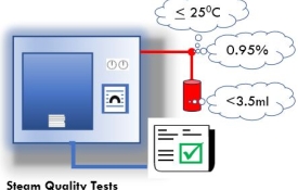
Non-condensable gas in the steam affects air dilution in the chamber. Water in the steam affects residual moisture in the load. Superheated steam can prevent or delay the formation of moist heat on the surfaces which need to be sterilized. Wide variations in delivery pressure to the sterilizer is indicative of inadequate steam capacity and this can affect the validity of thermometric measurements for assessing the presence of saturated steam. Contaminants can cause corrosion and deposit toxic substances on the product. When tested by the methods given in BS EN 285 the following should apply to the quality of steam supplied to the sterilizer: a maximum of 3,5 ml of gas collected from 100 ml of condensed steam; a minimum dryness value of 0,95 (5% moisture); a maximum of 25 °C of superheat when expanded to atmospheric pressure; contaminants fluctuations in steam pressure not exceeding ±10% of the nominal gauge pressure measured at the inlet to the final pressure reduction valve. ISO 17665:2024 - Annex C.10 A continuous supply of saturated steam is required for steam sterilization. Too high a level of non-condensable gases will prevent the attainment of sterilizing conditions; too little moisture carried in suspension can allow the steam to become superheated during expansion into the chamber, while excess moisture can cause damp loads. For all physical steam quality tests, the steam should be sampled from the steam service pipe to each sterilizer. The measurements are taken during a period of maximum steam demand, when steam is first admitted to the sterilizer chamber. Silicone rubber tubing is porous to steam and should not be used to carry steam in these tests. Steam pipework and sampling apparatus will be hot, and adequate precautions should be taken against getting burnt. Thermal gloves and safety glasses should be worn. Non-condensable gas test This test is used to demonstrate that the level of non-condensable gases in the steam will not prevent the attainment of sterilization conditions in any part of the load. Possible sources of non-condensable gases are discussed in paragraph 3.29, ‘Non-condensable gases’. The method described should not be regarded as measuring the exact level of non-condensable gas, but as a method by which the provision of acceptable steam quality can be demonstrated. Steam superheat test This test is used to demonstrate that the amount of moisture in suspension with steam from the service supply is sufficient to prevent the steam from becoming superheated during expansion into the chamber. The test assumes that the steam supply pressure is nominally 4.0 bar gauge. If the supply pressure differs from this it might be necessary to amend the acceptance criteria accordingly. Steam dryness test The accurate measurement of the percentage of moisture content in the steam is difficult, and the traditional methods, where constant steam flow is required, are not suitable for sterilizers. This test should be regarded not as measuring the true content of moisture in the steam, but as a method by which the provision of acceptable steam quality can be demonstrated. Possible sources of excessive moisture are discussed in paragraph 3.18, ‘Dryness’. The test is carried out immediately after the superheat test. Return to Schedule of Tests

These tests are used to verify that the design of the operating cycle, selection of the process parameters and the moisture contained in the steam are such that the level of moisture remaining in the load at the end of a sterilization process has not increased by more than 1% for textiles and 0.2% for metal. See BS EN 285 for the test method. ISO 17665:2024 - Annex C.8 This test prescribed in BS EN 285, clause 20, is used to demonstrate that the operating cycle, without extended drying, will not cause an increase in moisture in a standard test pack sufficient for there to be uncertainty about the dryness of loads routinely processed. The load dryness, metal test is performed with a reference load and is used to demonstrate that the operating cycle is unlikely to cause moisture problems in routine operational loads. If moisture problems are identified after the test has been successfully completed, the cause may be the type of load and location on the sterilizer chamber. It is therefore advisable, if possible, to process a routine operational or production load. Process a production load that is known to present the greatest challenge to the operating cycle. Extended drying may be required. The check should be considered satisfactory if a “cycle complete” indication is obtained, and the load is sensibly dry. Return to Schedule of Tests

The automatic control test compares the performance of an operating cycle with its specification, normally by visual observation. The user activates an operating cycle and then observes each stage, noting the pressure and temperatures attained at each of the cycle switching points. The observed values are then compared with the specified values to ensure they remain within the defined tolerances for the cycle. Modern sterilizers carry out this test automatically using a control and monitoring system. ISO 17665:2024 - Annex C.11 Introduction In order to test the functionality of the operating cycle an automatic control test can be performed. The test checks the indicated and recorded cycle variables from instruments fitted to the sterilizer. Typically this test would be done as part of initial validation and then weekly as part of a periodic test routine. It is the main test for ensuring that the sterilizer continues to function correctly, as validated. During commissioning and validation testing temperature and pressure sensors will be connected to the sterilizer for thermometric testing. If one sensor is located in the reference measurement point (usually the active chamber discharge or drain) then the calibration of the sterilizer instrumentation may be conveniently checked during the holding time of the automatic control test. Test Procedure For porous load sterilizers, place a standard test pack in the chamber, with the bottom of the pack supported 100-200 mm above the centre of the chamber base, (leave the chamber empty except for the usual chamber furniture). For fluid sterilizers, for installation and commissioning tests, leave the chamber empty except for the usual chamber furniture. For periodic tests, load the chamber with a production load of a type for which a record has been established during performance qualification. If the test proves satisfactory, the sterilized load may be released for normal use. Sterilizers designed for fluid loads equipped with one or two load sense probes to record the temperature of the load. If a production load is being processed, insert the probes into the load in the positions they would normally occupy. Otherwise stow the probes in accordance with the manufacturers recommendations. Select the sterilization temperature for the operating cycle to be tested. As a rule, this should be the highest temperature compatible with the load. If a production load is being used, select the temperature at which it would normally be sterilized. Start the cycle. Ensure that a process record is made by the recording instrument fitted to the sterilizer. Where a sterilizer does not have a process recorder, observe and note the elapsed time, indicated chamber temperatures and pressures at all significant points of the operating cycle, for example the beginning and end of each stage or sub-stage, and the maximum values during the holding time. At the approximate mid-point of the plateau period, note the elapsed time and indicated chamber temperature and pressure. For fluid loads, as soon as the cycle is complete, but before opening the door, observe and note the recorded temperature in the containers. The test should be considered satisfactory if the following requirements are met: - a visual display of cycle complete is indicated; during the whole of the cycle the values of the cycle variables as shown on the batch process record are either within the limits established by the manufacturer as giving satisfactory results, or, for production loads, within the permitted tolerances marked on a master process record subsequently established during performance qualification; during the plateau period determined from the recorded chamber temperature: the indicated and recorded chamber temperatures are within the appropriate sterilization temperature band. the difference between the indicated and recorded chamber temperature does not exceed 2°C; the difference between the indicated and recorded chamber pressure does not exceed 0.1 bar; the holding time determined from any load temperature probes is not less than that specified in the appropriate sterilization temperature band. during the holding time, any temperatures recorded in the load are within the appropriate sterilization temperature band; the door cannot be opened until the cycle is complete; for fluid loads, at the end of the cycle the temperature recorded in the containers is not greater than 90°C (plastic) or 80°C (glass); the person conducting the test does not observe any mechanical or other anomaly. Return to Schedule of Tests

0 Air Detector Tests - Performance and Function
These tests are used to set the air detector to register a fault whenever residual air is sufficient to cause a failure of the small load test and the full load test. The air detector should register a fault when, at the commencement of the equilibration time, residual air causes a difference of more than 2°C between the lowest temperature measured in the standard test pack and the temperatures measured at the reference measurement point of the chamber. In certain applications and setting (e.g. industrial settings) the performance of the air detector can be based on the defined process parameters and the product of product family(ies) that the sterilization process is designed to process. ISO 17665:2024 - Annex C.7 Introduction Where a sterilizer employs vacuum as a means of removing air for the load prior to sterilization an air detecting system may be installed and used to determine whether any air or non-condensable gas present in the chamber is sufficient to impair the sterilizing process. The air detecting system should cause a fault to be indicated if the amount of air or gas in the chamber at the start of the plateau period is sufficient to depress the temperature in the centre of the load more than 2°C below the temperature in the reference measurement point, (typically the drain). Correctly set up and air detector will enhance the security of the product sterilized. It is not an alternative process to effective planned preventative maintenance or other recommended periodic tests, such as the Air Leakage Flowrate Test or Bowie and Dick Test. Test Procedure Advice should be sought from the sterilizer manufacturer who can advise on the correct settings for the air detector. The process of setting up the air detector can be lengthy and complex in the absence of manufacturers guidance and information. Typically, the manufacturers should be able to provide the following information: - The default sensitivity set point of the air detector system that will cause the sterilizer control system to indicate a fault condition. The set point which will trigger the air detecting system check. The level of vacuum leak rate that will cause this level to be exceed. Verify that the chamber integrity is satisfactory by performing an Air Leakage Flowrate Test. Once satisfied there are three tests to be performed in sequence, the small load, full load and function test. Prior to commencing the tests, install an air-flow metering device to the chamber, usually by means of the port provided by the manufacturer for connection of test sensors. Performance test for the air detector, small load This test is designed to determine the setting for the air detector so that, with a small load, it will respond to a leak rate sufficient to depress the temperature in the test pack by no more than 2°C. Follow the set-up procedure for the Thermometric Test Small Load If the air detector is correctly set, the test should proceed rapidly down the left-hand branch and be complete in two cycles. Select the operating cycle with the highest sterilization temperature and standard drying time. Place a standard test pack in the chamber, with the bottom of the pack supported 100-200 mm above the centre of the chamber base. A fresh test pack is required for each test. At the start of the test ensure that the air detector sensitivity is set to the value recommended by the manufacturer. The detector can be disabled in accordance with the manufacturer’s instructions. During the air removal stage, admit air into the chamber by means of the air-flow metering device at the level sufficient to depress the temperature in the centre of the load more than 2°C below the temperature in the reference measurement point, (typically the drain). NOTE: BS EN 285:2015, clause 19.2.2.9 instructs that the can be necessary to conduct a number of tests in order to establish the level of induced air leakage required. If the induced air leakage is found to exceed 11.0 mbar/min it recommends setting the induced leak rate to 10mbar/min (+/-1.0mbar/min), (clause 19.2.2.11). I would recommend that the test person starts this sequence of tests with a leak rate of 10mbar/min (+/-1.0mbar/min). See further reading Air Detectors From the measured temperatures, determine the temperature depression at the start of the plateau period: Depression, Δ T = Tc -Tp where: Tc = temperature measured in the active chamber discharge; Tp = temperature measured in the centre of the test pack. When the small load test is complete, proceed immediately to the air detector, fullload test. Performance test for the air detector, full load This test is designed to show that an air detector set to respond correctly during the small load test will also respond correctly with a full load. It is normally carried out immediately after a satisfactory completion of a small load test. If the air detector has been correctly set, the test should proceed rapidly, Select the operating cycle used for the air detector, small load test. The load is a standard test pack placed in the chamber in a position identified by the manufacturer as the most difficult to sterilize, with the remaining usable chamber space filled with a full load appropriate to the type of sterilizer under test, (see Thermometric Test Full Load). Place temperature sensors as for the Thermometric Test Small Load. A fresh load is required for each cycle At the start of the test ensure that the air detector sensitivity and leak rate settings are identical to those established in the air detector, small load test. If, during the test, it becomes necessary to readjust the air detector setting, repeat the small load test and verify the air detector settings. Function test The air detector function test is used to provide assurance that the setting of the air detector remains valid. This test is typically performed as part of the weekly schedule of tests. Set the air-flow metering device to the setting established during the air detector, small load test. Place a standard test pack in the chamber, with the bottom of the pack supported 100-200 mm above the centre of the chamber base. Select and start the operating cycle. The test should be considered satisfactory if the operating cycle is aborted and a fault is indicated. If the cycle is not aborted, then the advice of the manufacturer should be sought. When the air detector tests are complete, the settings of the air detector sensitivity, the automatic controller trigger point, and the air-flow metering device and induced vacuum leak rate should be noted in the test report. Product Load Where the performance of the air detector on the user’s production load (industrial settings) cannot be predicted from the above standard test loads, it may be necessary to repeat the air detector small and full load tests on the user’s load configurations. In the context of GMP operation the small and full load is typically the minimum and maximum load pattern for each load configuration. If the user load is a fixed load, I would recommend the full load be replaced with the users loading configuration. Return to Schedule of Tests

The air leakage test is used to demonstrate that the quantity of air leakage into the sterilizer chamber during periods of vacuum does not exceed a level that will inhibit the penetration of steam into the sterilizer load and will not be a potential cause of re-contamination of the sterilizer load during drying. ISO 17665:2024 - Annex C.6 Introduction The vacuum leak test is applicable to any sterilizer which employs vacuum to remove air from the load, such as a porous load sterilizers and some fluids sterilizers. Leakage of air into the chamber at a rate greater than that specified below is unacceptable for the followings reasons: the presence of air inhibits penetration of the load by the sterilant and prevents sterilization; air leaking into the chamber during the drying and air admission stages will not have passed through the bacteria-retentive filter, and therefore there is a risk of recontamination of the load; A vacuum leak test is required to establish that permissible limits are not exceeded. The test is performed by measuring the change of vacuum in the chamber when all valves leading to it have been closed and the vacuum source isolated. NOTE- If the test is conducted as part of a programme including thermometric tests, it will be necessary to repeat it with the temperature sensors and any test pressure gauge in place, and again when they have been removed, to ensure that there is no leakage through the ports. The test should be performed with an empty chamber. If the sterilizer is not fitted with a vacuum leak test instrument, connect a 0-160 mbar absolute pressure gauge to the chamber. For the test to be accurate, the chamber temperature should be stable. For example, in a closed vessel at 40 mbar absolute, the pressure changes by approximately 1 mbar for each 10°C change in temperature over the range 20-140°C. At 70 mbar the change is approximately 2 mbar. The test could be compromised if the temperature changes by more than 10°C during the period in which the chamber pressure is monitored. Stabilise the temperature of the chamber by one of the following methods: If the vessel incorporates a heated jacket, carry out an operating cycle with the chamber empty; If there is no heated jacket, ensure that the temperature of the chamber is no greater than 20°C from ambient. When the temperature has stabilised, start the vacuum leak test cycle. For automatic systems the following steps are performed automatically, and the vacuum leak rate is displayed as a pressure rise in mbar min-1. For semiautomatic systems, the pressures should be read and noted by the operator. When the pressure in the chamber drops below 50 mbar absolute close all the valves connected to the chamber and stop the vacuum pump. Note the time and the absolute pressure (P1). Wait for 5 minutes (± 10 s), and then note the pressure again (P2). Wait for a further 10 minutes (± 10 s), and then note the pressure for a third time (P3). Restore the operating cycle and allow it to proceed normally. Calculate the vacuum leak rate for the 10-minute period from: Vacuum Leak Rate = (P3-P2)/10mbar min-1 For chambers with a capacity of 250-600 I, the test should be considered satisfactory if the following requirements are met: the absolute pressure (P2) at the start of the 10-minute period is: less than 70 mbar for porous load sterilizers; the vacuum leak rate does not exceed: 1.3 mbar min-1 for porous load sterilizers and laboratory sterilizers; For chambers outside the range 250-600 I, the test should be considered satisfactory if the pressure P2 and the vacuum leak rate are as specified by the manufacturer. Considerable care must be applied in the interpretation of the results of leak tests. On a typical test on a porous load sterilizer the pressure may rise by 20 mbar or more (P2 – P1) in the first 5 minutes of the test due to the evaporation of moisture remaining in the chamber and connecting pipework. Such a result does not necessarily indicate a leak. A machine which fails to meet the requirements of this test should not be used until the fault has been rectified and the test satisfactorily completed. Return to Schedule of Tests

This is a test for steam penetration into the maximum size of load intended to be processed in the steriliser and complements the small test. The textile test pack is located in the centre of a full load of textiles. The test load is designed to represent the maximum mass of textiles which can be processed in the steriliser and is used to demonstrate that, at the levels at which cycle parameters are set, rapid and even penetration of steam into the centre of the load occurs sterilizing condition is achieved. ISO17665:2024- Annex C.4.2 Introduction The full-load test is designed to demonstrate that, at the levels at which cycle variables are set, rapid and even penetration of steam into the centre of a load occurs, and the sterilizing condition is achieved in a test load of specified maximum mass and of sufficient size to fill the usable chamber space. Temperatures and pressures should be recorded by independent measuring equipment. Test Method Place the standard test pack within the chamber in a position identified by the manufacturer as the most difficult to sterilize. This will normally be in the approximate centre of the chamber. Place three temperature sensors in the following positions: one in an active chamber discharge; five within the test pack as detailed in BS EN 285 (the wire from the sensors should be carefully arranged to prevent steam tracking along it); one below the approximate centre of the top sheet of the test pack. Load the rest of the usable chamber space with stacks of sheets. (The mass of fabric in the load should be equivalent to 7.5 ± 0.5 kg for a unit volume 300 mm x 300 mm x 600 mm.) Connect a pressure recorder (or test gauge) to the chamber. Start the operating cycle, with standard drying time, and take readings as described for the automatic control test. If a pressure recorder is being used, measure the chamber pressure at the approximate mid-point of the holding time. The test should be considered satisfactory if the following requirements are met: the requirements of the Automatic Control Test are met; the equilibration time determined from the measured temperatures does not exceed 15 s for chambers up to 800 I and 30 s for larger chambers; the holding time determined from the measured temperatures is not less than that specified for the selected sterilization temperature; during the holding time: the measured temperatures are within the appropriate sterilization temperature band for the selected sterilization temperature; the measured temperatures do not fluctuate by more than ± 1°C; the measured temperatures do not differ from one another by more than 2°C; the indicated and recorded chamber temperatures are within 1°C of the temperature measured in the active chamber discharge; the indicated and recorded chamber pressures are within 0.05 bar of the measured pressure; the total cycle time is within the performance class stated by the manufacturer; at the end of the cycle the sheets are sensibly dry. Return to Schedule of Tests